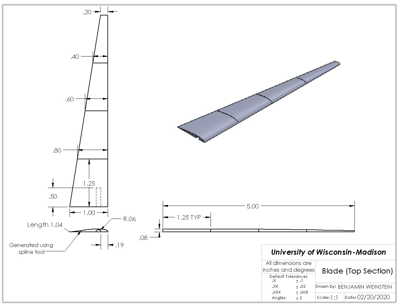
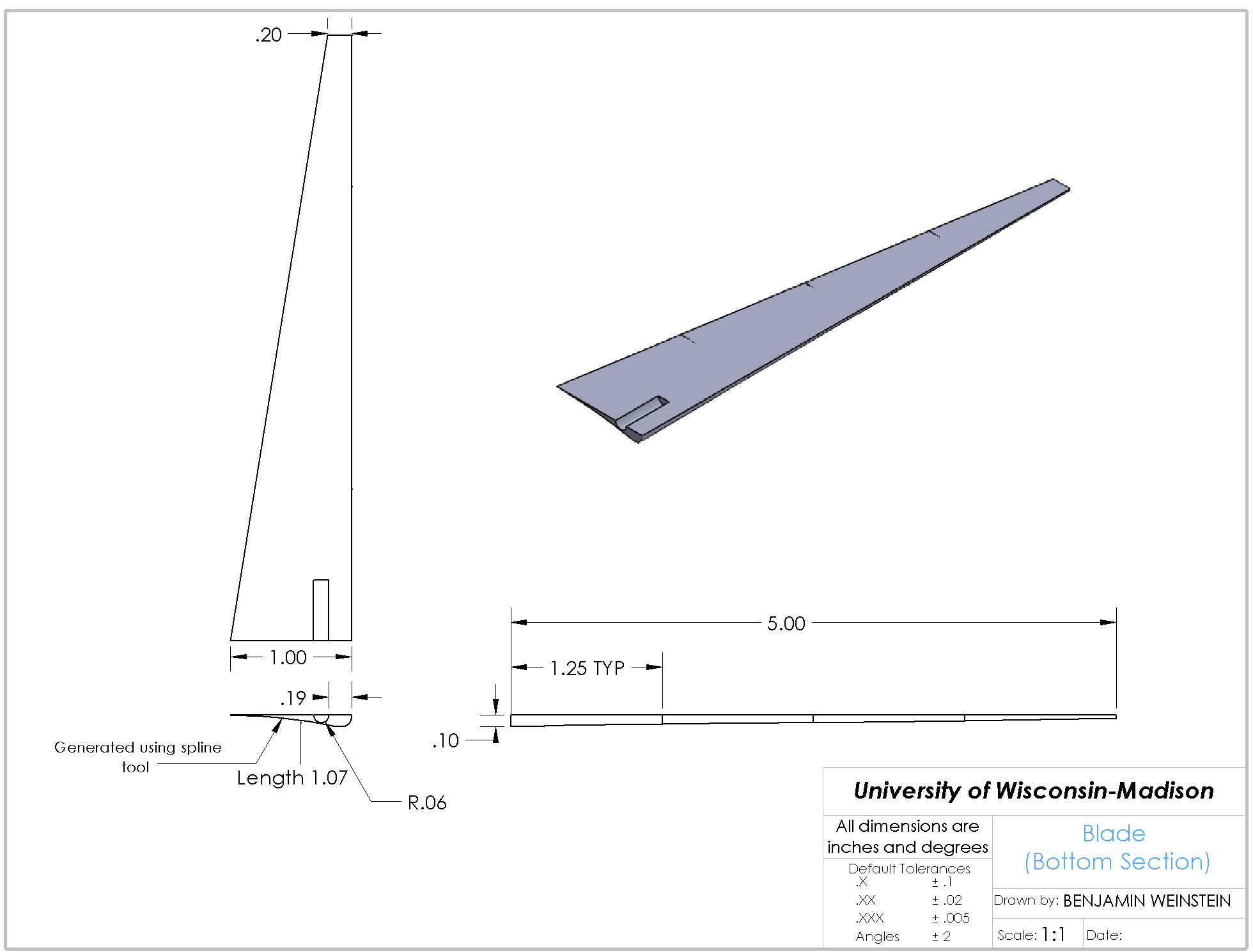
This project was a part of my Intro to Mechanical Engineering class. As a practical exercise in test design and design optimization, we were directed to build a small wind turbine model and figure out which parameters would affect efficiency the most. My partner and I first decided which two variables we wanted to test, eventually settling on the number of blades and blade pitch. I then modeled a basic airfoil in Solidworks, and created two variants of blade hubs to fit a 3-blade and a 4-blade version. Because I planned to 3D print the blades, I initially made the top and bottom halves as separate pieces which could be printed then glued together, with a pin to attach to the hub.
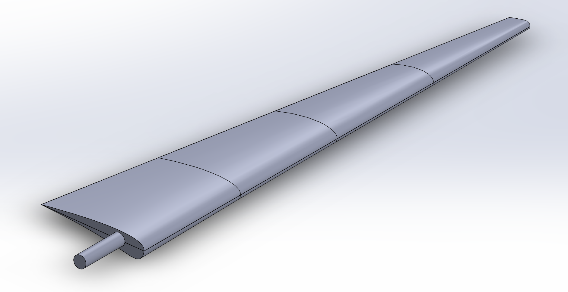
The first print was not optimal, with a lot of warping and having to glue together the blades resulted in damage and non-aligned surfaces. Additionally, I was not able to use FFF 3D printing like I had planned, so the split blade was no longer optimal. I ended up rethinking how I approached the printing process and decided to try printing the entire blade assembly as one piece. The model I sliced and the initial test print are shown below, along with the 4-blade hub. The test print still had some minor warping, so I used a stiffer resin for the SLA printing of the final blades.
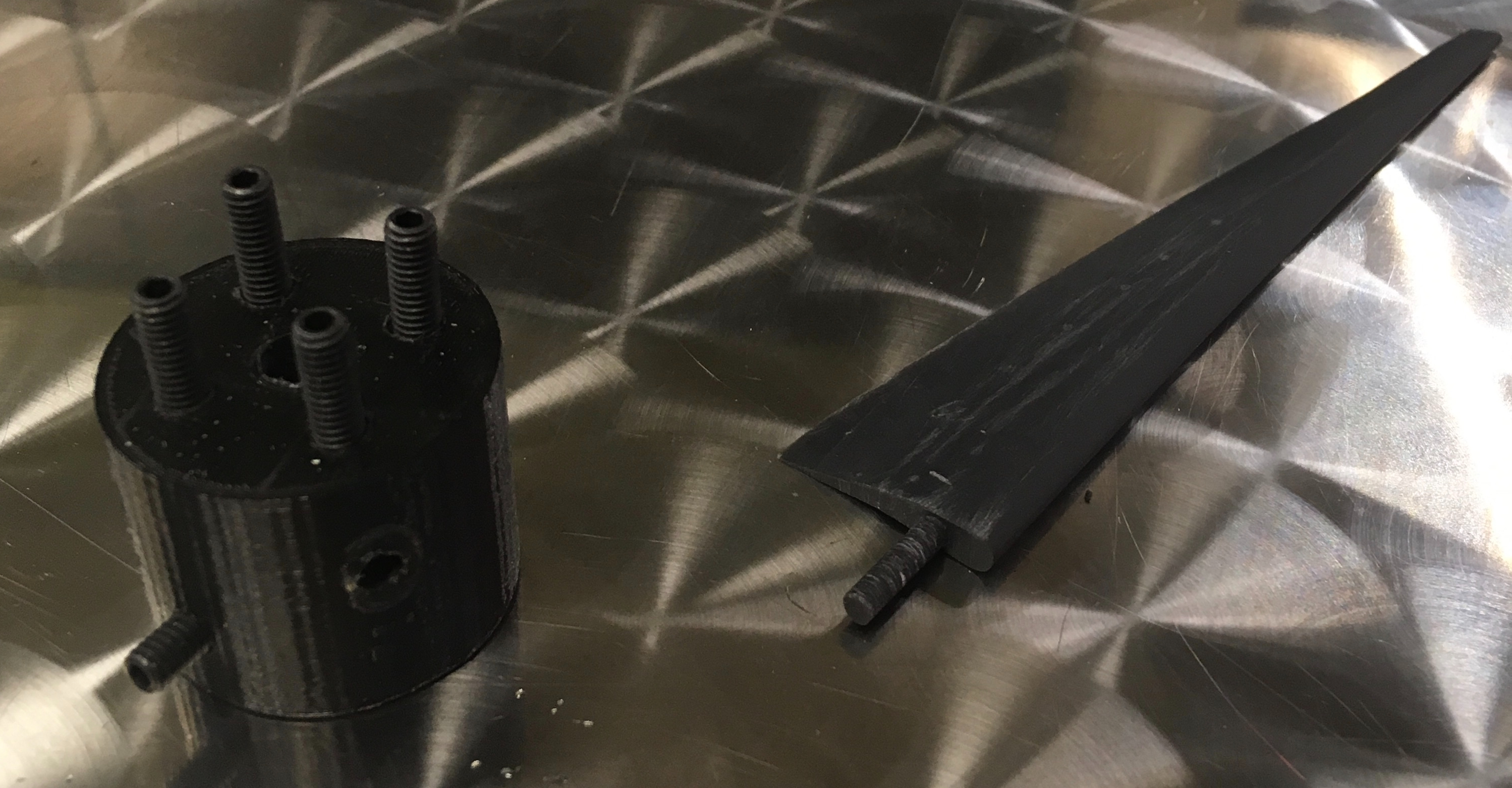
Unfortunately, due to COVID-19 we never got to test this model– we completed the project with sample data. However, I was able to assemble the final printed blades and do a test to see if they would actually work as airfoils. This prototype test was a success! The turbine blades spun well, and the set screws on the hub allowed for easy pitch adjustment while keeping the blades secure in the housings.
